WHITE NOTES
Threshold of Hearing
Graphical representation of the human threshold of hearing.
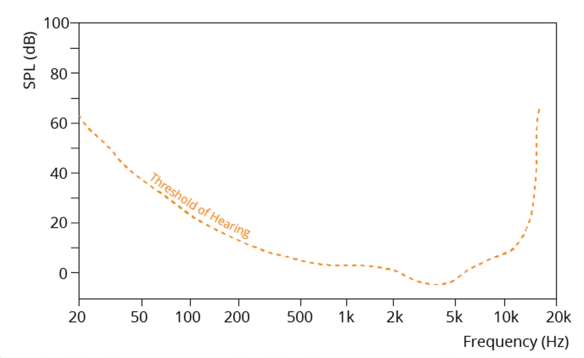
The dashed line represents the threshold between what is audible and what is not to the human ear. In order for the sound at a particular frequency to be perceivable, the SPL must be above the line.
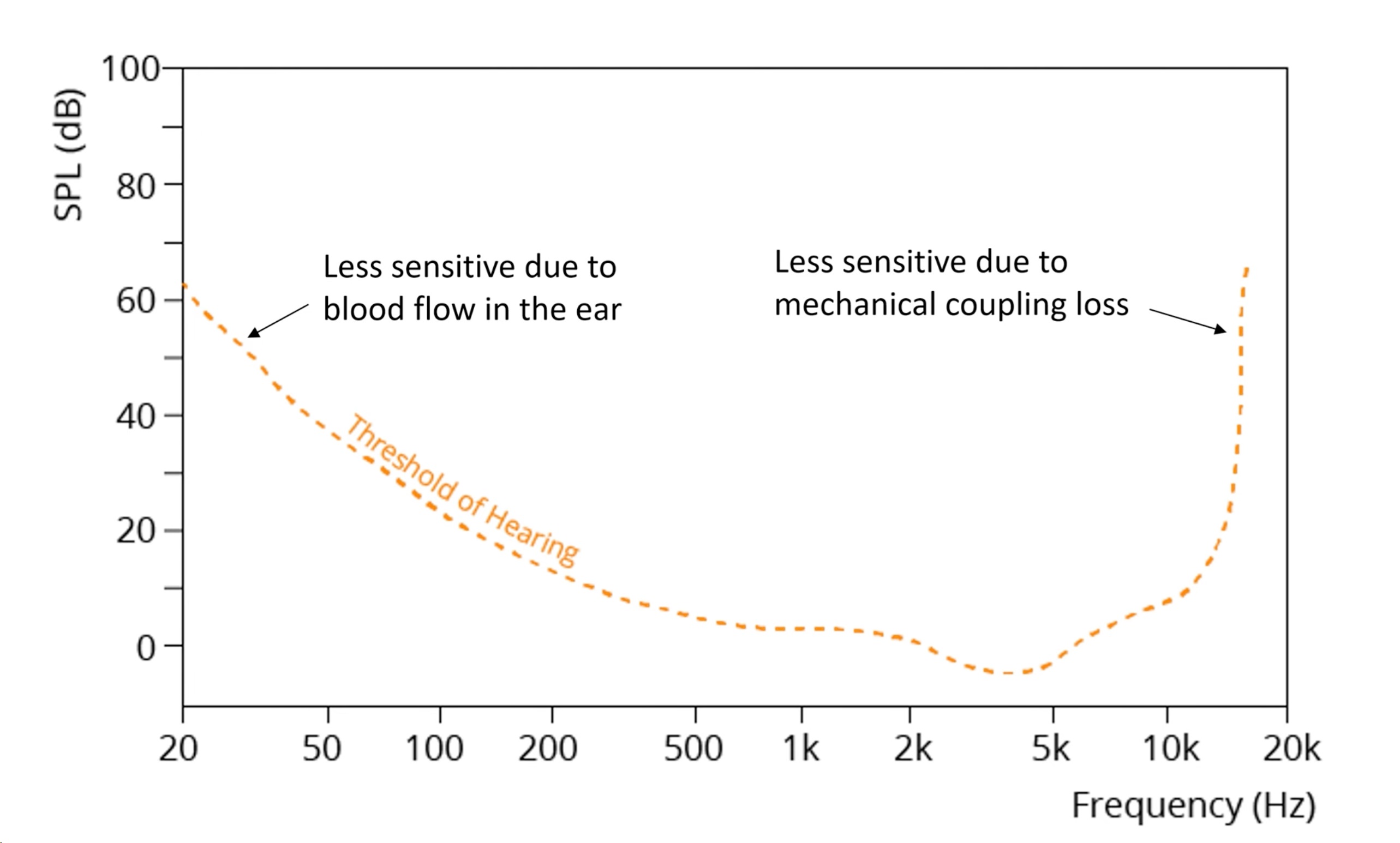
Toward the extremes of the audible frequency spectrum, the SPL required for sound to be perceived increases due to limitations in the human auditory system.
Exciter Speakers Application Notes
Exciter speakers (also called surface transducers or vibration speakers) are specialized audio transducers that convert electrical signals into mechanical vibrations. Instead of radiating sound directly through a cone like a standard speaker, they transfer vibrations into a surface (panel, glass, metal, plastic, wood, etc.), turning that surface into a sound-radiating diaphragm.
Consumer Electronics:
Portable speakers, TVs, laptops, AR/VR devices
Automotive:
Hidden speakers in dashboards, headliners, and glass
Appliances:
Voice assistant output in smart appliances
Industrial / Public Installations:
Kiosks, digital signage, ATMs (audio feedback without exposed speakers)
Specialty Uses:
Haptics (touch feedback), bone conduction in specific designs
Invisible installation
Exciters can be mounted behind surfaces, preserving aesthetics.
Distributed sound
Larger radiating surface for wide dispersion and no distinct source point.
Customizable sound signature
Tone and volume can be shaped by surface material and size.
Surface Material
Tonal Character
Advantages
Considerations
Bright, clear highs; crisp
Invisible mounting, aesthetic
Less bass; can sound harsh if very thin
Fuller sound, natural resonance
May need bracing to reduce rattles
Plastic (ABS, polycarbonate)
Panel thickness and stiffness strongly affect the tone.
Can sound “tinny”; may need damping
Mounting Guidelines
Firm and flush mounting
Essential for efficient vibration transfer to the surface medium.
Avoid gaps
Between the exciter and the surface. Adhesive pads or screws are common.
Positioning
Mount near the center for balanced output, near an edge for higher sensitivity.
Panel size and stiffness
Larger, thinner panels provide more bass but less clarity. Smaller, stiffer panels give better high-frequency detail.
Impedance
Common values are 4Ω or 8Ω; match to amplifier output.
Power Handling
Typically 3–30W RMS, depending on the exciter model.
Frequency Response:
Depends heavily on mounting surface. Typical useful range: 100Hz to 18kHz.
Amplifier Requirements:
Use an amplifier with a low distortion output to avoid distortion being passed to the exciter, which can damage the exciter or surface. Consider using a high-pass filter (80–100 Hz) to protect the exciter from excessive excursion at low frequencies.
Single Exciter on One Panel
Design Tips for Single Exciter Systems:
Larger, thinner panels
More bass but less clarity.
Smaller, stiffer panels
Better clarity but less bass.
Multiple Exciters on One Panel
How This Works
Two exciters are mounted on the same panel, spaced apart (ideally on opposite halves) where each exciter is connected to its own amplifier channel. The panel becomes a shared diaphragm, but with stereo imaging such that the left channel vibrations dominate near Exciter 1 and right channel vibrations dominate near Exciter 2. A stereo design works best with a wide, stiff surface (glass, wood, composite).
Design Tips for Multi-Exciter Systems
Panel Size
Bigger panels reduce interference between left and right channels.
Spacing
Maximize the distance between exciters for better stereo separation.
Damping
Add strategic damping (felt, foam) to reduce cross-talk between channels if needed.
Power
Use matched amplifier channels to prevent imbalance.
Prototyping is essential
The sound output depends on the surface, so test with intended materials early in development. Theorizing the output will often not lead to a comprehensive understanding of the end output.
Multiple exciters
Using two or more exciters can improve output power and create a more uniform sound field.
Isolation
Avoid mounting surfaces that share contact with sensitive electronics to prevent vibration issues. Use vibration absorption mediums between mounting surfaces and sensitive electronics.
Haptics
For tactile feedback, choose smaller, stiffer mounting surfaces and tailor the drive waveform to the resonance of the mounting surface.
Operating Environment
Avoid exposure to moisture unless rated for it.
Surface fatigue
Long-term high-volume use may loosen adhesive bonds. Mechanical mounting is more robust for permanent installations.
Thermal
Ensure adequate ventilation for high-power applications. Exciters dissipate heat through their contact surface.
A frameless TV with invisible audio using glass panels as speakers.
An interactive kiosk with an exciter hidden behind a metal panel, providing audio without exposed components.
A smart appliance using a small exciter behind the plastic housing for voice prompts.
Summary
Exciter speakers offer unique opportunities for invisible, wide-dispersion audio output in products where space, design, or aesthetics prohibit the use of traditional speakers. Correct surface selection, mounting technique, and amplifier matching are critical for achieving optimal performance.
IEC 60601-1-8 – Alarm Systems in Medical Electrical Equipment
IEC 60601-1-8 specifies requirements for alarm systems in medical electrical equipment and systems, focusing on:
Ensuring safe and effective communication of alarm conditions
Helping operators prioritize patient care
Reducing nuisance alarms and alarm fatigue
The standard has been updated in 2020, and the following details are reflective of this update.
Applies to:
Medical electrical equipment (MEE) and systems (MES) using audible, visual, or tactile alarms
Standalone and integrated alarm systems indicating potential or existing hazardous conditions
Excludes:
Alarms in medical software not part of an ME system
Non-medical general-purpose alarm systems
The standard has provided a distinction between two types of auditory signals:
Audio Icon:
A structured sound pattern that conveys specific information about the type or source of an alarm condition (e.g., low oxygen saturation, cardiac arrhythmia).
Audio icons follow strict requirements for tone duration, frequency range, and repetition to ensure they are recognizable and appropriately prioritized.
Auditory Icons vs. Abstract Sounds
Auditory Icons (real-world, familiar sounds) are more easily learned, recognized, and remembered than abstract alarm tones.
They offer better localization, resistance to masking, and less confusion with natural clinical environment sounds.
Icons must be paired with auditory pointers to be most effective.
Auditory Pointer
Serve to indicate the priority level (high, medium, low) and the source of the alarm.
Designed using psychoacoustic principles for urgency perception, audibility, and localizability.
Key urgency cues include pitch, repetition rate, amplitude, and harmonic complexity.
Loudness is a less reliable indicator of urgency due to ambient noise variability and potential for startle.
Alarm Signal Types
Auditory: Tone
Visual: Indicator light, Text
Tactile (optional): Vibration or other physical cues
Alarm Signal Priority Levels
High: Immediate response to life-threatening situations
Auditory signal: Loud, sharp, urgent (within 5 seconds)
Visual signal: Red, may flash
Distinctive sound patterns
Medium: Prompt response required
Auditory signal: Moderate tempo and volume
Visual signal: Yellow/amber
Low: Awareness needed, no immediate danger
Often visual-only (blue, green, or white); optional soft auditory signal
Auditory Alarm Signals Overview
Unique and distinct patterns for each priority
Recognizable within 5 seconds
Not overly disruptive
Predefined melodies/rhythms for physiological conditions (e.g., apnea, arrhythmia)
Category of the Source of the Alarm Condition
Auditory Icon Metaphor
Auditory Icon Description
“Lup-dup”; heartbeat sound
A stylized, square/triangle wave-based "heartbeat" sound with no discernible frequency. Six PULSES formed from three 2-PULSE "lup-dup" sequences
Liquid disturbance, water churning, bubbles
Two approximately 1 s sequences of a strong water bubbling sound, separated by silence
A single inhale followed by an exhale
A 1 s inhaling sound (like white noise), followed by a 0.5 s gap, followed by a slow exhale with a long tail
Irregular, stylized dripping/saturation
Stylized irregular temporal pattern with some discernible pitch; a two-tone sequence superimposed on the six-tone pattern
Temperature/Energy Delivery
Complex sound including high frequency harmonics, rising slowly over approximately 2 s
Drug or Fluid Delivery/Administration
Two 0.8 s sequences of a 4- rattle shaking sound
Equipment or Supply Failure
Starting up a motor that shuts down suddenly
Spectrally complex sound of a motor revving up (increasing in frequency) over approximately 1.2 s then an abrupt stop tailing off for approximately 0.5 s
The “general” category has no "Auditory Icon”; only an Auditory Pointer is used.
Primary Frequency: 150 Hz to 1,000 Hz
Frequency Components: 4 frequency peaks between 150 Hz and 4,000 Hz
Component Loudnesses: Relative sound pressure levels of the four frequency components with the largest sound pressure levels should be within 15 dB of each other
Sound Level: 5-15 dB above ambient, depending on priority
High Priority Alarm
Number off Pulses in Burst: 10
Pulse Duration: 25 – 75 ms per tone
Pulse Spacing: Varying depending on pulse number
Interburst Interval: Every 2.5 to 15 seconds
Frequency Pattern: Clearly defined, descending or attention-grabbing
Sound Example: Beep-beep-beep (pause) beep-beep-beep
Medium Priority Alarm
Number off Pulses in Burst: 3
Pulse Duration: 90 – 200 ms per tone
Pulse Spacing: Between 50 – 100 ms
Interburst Interval: Every 2.5 to 30 seconds
Frequency Pattern: Distinguishable but less urgent than high priority
Sound Example: Beep-beep (longer pause) beep-beep
Low Priority Alarm
Number off Pulses in Burst: 1 or 2
Pulse Duration: 400 – 600 ms
Interburst Interval: >15s or no repeat
Sound Level: Quiet or optional auditory signal
Sound Example: Beep .......... beep (widely spaced)
Rise and Fall Time
Rise Time: 10 – 20 % of Pulse Duration (from 10% to 90% amplitude)
Should not be so short as to create mechanical noise.
Audible distortion can be created in these instances due to mechanical limitations of the audio component
Fall Time: Less than the Pulse Spacing minus the Rise Time (from 90% to 10% amplitude)
Should be short enough to ensure pulses do not overlap
Avoids clicking, popping, or distortion.
Tones must be distinguishable from background noise
Alarm tones must avoid musical patterns for high priority
Systems must balance urgency without causing startle or alarm fatigue
Consistency across equipment enhances recognition and response
Must indicate:
Alarm condition
Source or affected parameter
Alarm priority
Color Coding:
Red: High Priority (Flicker: 1.4 – 2.8 pulses/second)
Yellow: Medium Priority (Flicker: 0.4 – 0.8 pulses/second)
Blue/Green/White: Low Priority (Continuous illumination)
Support latching/unlatching of alarms
Provide acknowledgement functions
Allow limited-time silencing
Store historical alarm logs
Alarm systems must undergo:
Risk Management: (ISO 14971)
Usability Engineering: (IEC 62366)
Manufacturers must validate:
Signal audibility and intelligibility
Visual indicator visibility and legibility
Correct prioritization and system response
Design must minimize alarm overload and fatigue
Systems must function under single fault conditions
Failures must trigger clear and safe alerts
Note: These White Notes are for reference purposes only. For accurate design guidelines, please reference the IEC 60601-1-8 standard directly.
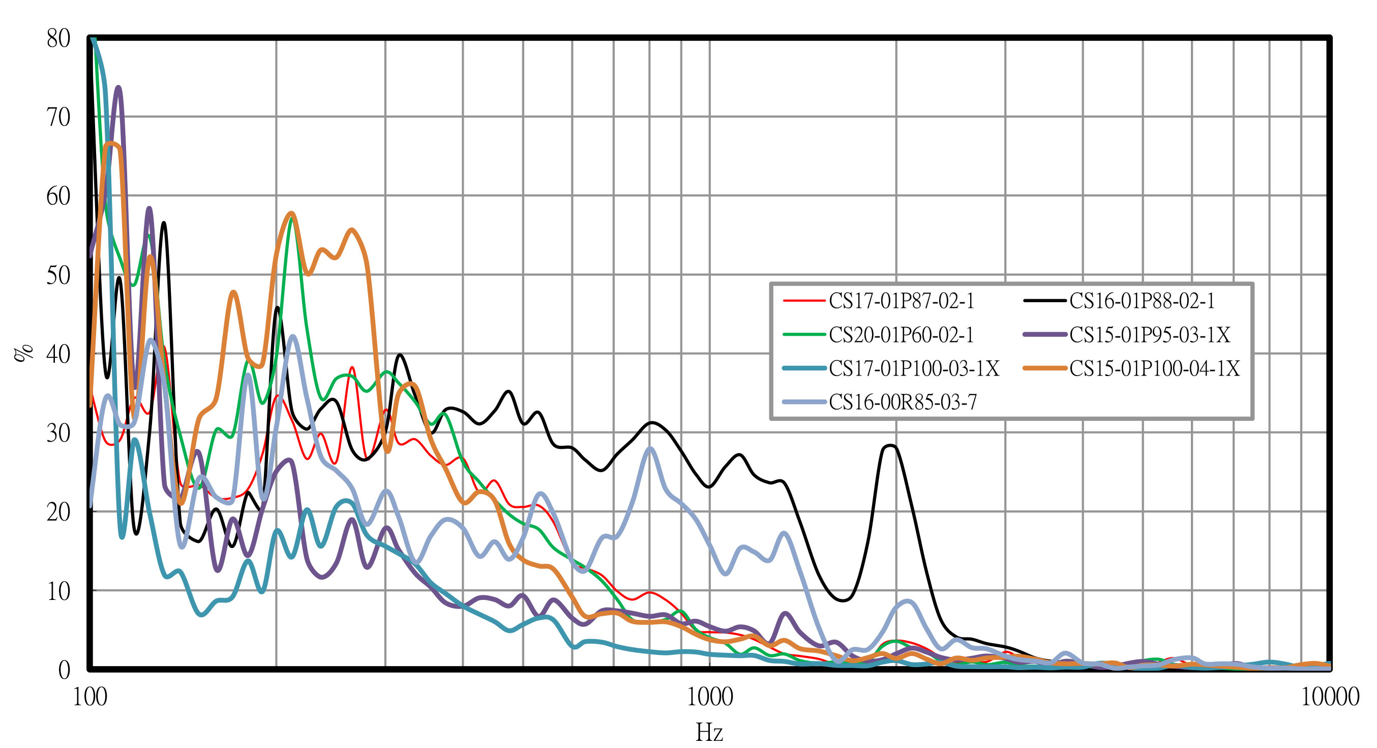
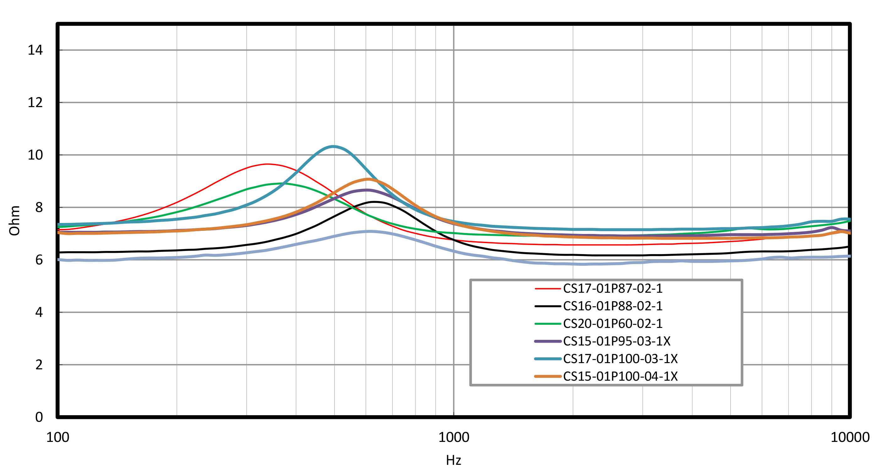
Mobile Speaker Performance Comparison
Graphical size to performance comparison of Challenge Electronics’ mobile speakers.
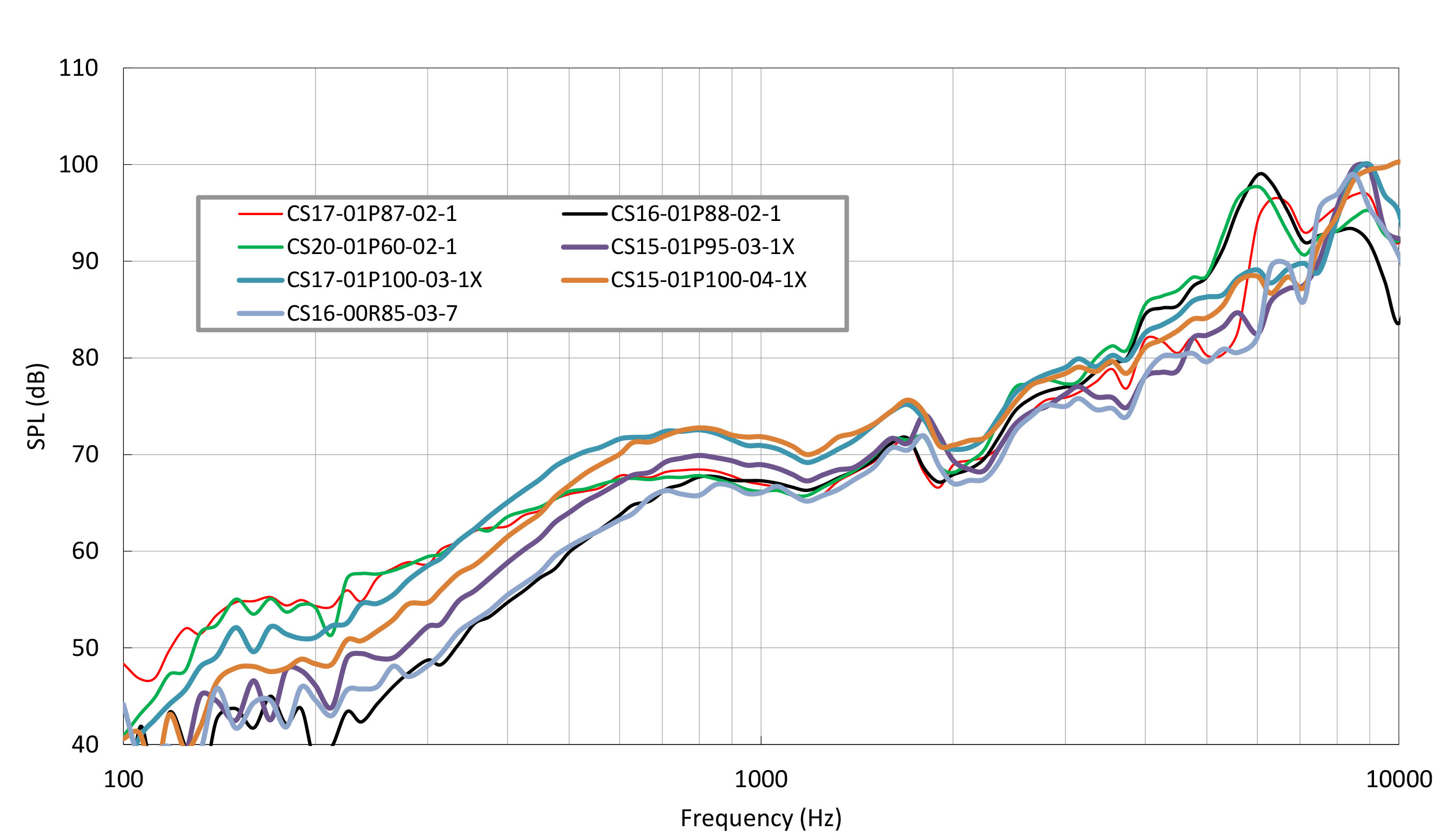
1V, 10cm, and in Recommended Sealed Chamber
1V, 10cm, and in Recommended Sealed Chamber
1V, 10cm, and in Recommended Sealed Chamber
Thiele-Small Parameters
The Thiele-Small parameters are a set of measurements that describe the electrical and mechanical properties of a speaker. Using these parameters, you can calculate the recommended size of a speaker box to achieve optimal performance. Here's a step-by-step guide.
1. Fs (Resonant Frequency):
This is the frequency at which the speaker naturally resonates when suspended in free air.
2. Qts (Total Q):
Qts is a parameter that combines the electrical and mechanical damping of the speaker. It influences the speaker's response in a closed-box system.
3. Vas (Equivalent Volume of Compliance):
Vas is a measure of the air volume that has the same compliance as the speaker's suspension system.
1. Determine the Desired Qtc:
Qtc is the total Q factor for the closed-box system. A common value for Qtc in sealed boxes is around 0.707 for a critically damped response.
2. Use the Qtc Formula:
The formula for Qtc in a closed-box system is Qtc = Qts / (Qtc + Qes).
Solve for Qes: Qes = Qtc / (1 - Qtc).
Use the obtained Qes in the next step.
3. Calculate Qes / Qts:
Qes / Qts is a correction factor. Multiply this factor by Vas to obtain the effective Vas for a sealed box: Vas_corrected = Vas * (Qes / Qts).
4. Determine the Box Volume (Vb):
Use the Vas_corrected to calculate the box volume using the formula: Vb = Vas_corrected / 0.85.
The 0.85 factor is an approximation for the air density and speed of sound in the box.
5. Convert Volume to Dimensions:
Use the calculated volume (Vb) to determine the dimensions of a rectangular box.
For a sealed box, the dimensions can be determined based on the desired shape (e.g., cube, rectangular prism).
6. Adjust for Driver Displacement:
Account for the space occupied by the speaker driver and any internal bracing. Subtract these volumes from the calculated box volume.
7. Verify:
Use specialized speaker box design software or online calculators to verify and refine your calculations.
It's important to note that these calculations assume an idealized environment, and real-world factors such as room acoustics and specific driver characteristics may require adjustments. Additionally, these calculations are specific to sealed-box designs, and other enclosure types (vented, bandpass, etc.) have different formulas and considerations.
Circuit Applications
Challenge Electronics provides a variety of sound transducers, both piezoelectric and electromagnetic. To power these devices, we have a variety of drive circuit options that we recommend you use for optimal performance from our parts. The below are offered only for reference.
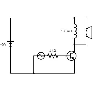
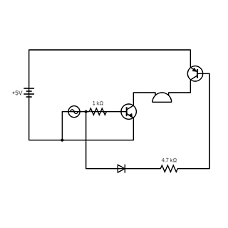
The Electromagnetic Drive Circuit shown is the typical circuit used for electromagnetic transducers. The positive pin of the transducer is connected to a DC voltage source while the negative pin is connected to the collector of the npn transistor. The emitter of the transistor is connected to ground. The base of the transistor is connected to the AC signal source.
The DC source determines the amplitude of the signal while the AC source determines the frequency. Once both are supplied, the transistor will sound at the given frequency.
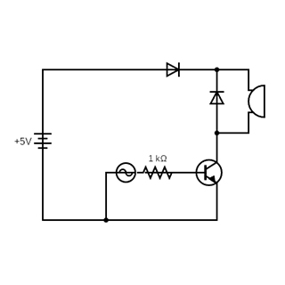
Electromagnetic Drive Circuit
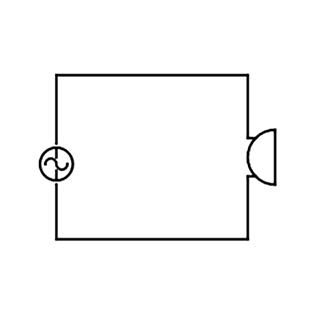
AC Signal Drive Circuit
The AC Signal Drive Circuit is the simplest drive circuit for a piezoelectric sound transducer. The positive pin of the transducer is connected to one end of the AC source while the negative pin is connected to the other. An AC signal is then applied across the transducer. While this can be a sine signal, a square signal is recommended instead as the sharp change from alternating voltage peaks and vice versa causes the piezoelectric element to bend quicker and more forcibly which produces higher SPL.
The limitation of this type of circuit is that the voltage range is determined by the limitations of the AC generator which are typically lower than a DC power supply.
To extend the range, the user could use the same Electromagnetic Drive Circuit shown before with some slight variations to account for the transducer being a piezoelectric device. Here, the limit will be the DC power supply and the AC power supply only needs to be high enough to supply a discernable high and low input signal to enable the transistor.
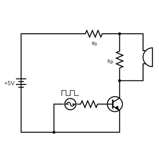
Piezoelectric Drive Circuit
Rp is a discharge resister to ensure there is a path for stored charge in the piezoelectric disk to discharge safely and can be between 600 ohm to 1,000 ohm.
Rs can be used optionally to adjust the loudness of the piezoelectric transducer.
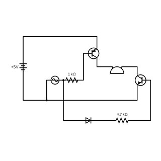
Resonant Drive Circuit
In either of the above cases, the circuit requires a high voltage source to achieve high SPL which can be impractical especially with portable devices. To achieve higher SPL with a lower voltage supply, the Resonant Drive Circuit above can be used.
Here, an inductor is introduced into the previous circuit. An inductor resists instantaneous changes in current. When the transistor switches from on to off, the flow of current should ideally be cut. The inductor, however, wants to maintain whatever current is flowing through it and so will compensate by introducing a sharp temporary voltage spike that is greater than the supply voltage. The piezoelectric element will bend in response to the voltage spike and produce an SPL higher than what it would without it.
To maximize the gain with this addition, the chosen inductor needs to be selected based on the capacitance of the piezoelectric element such that the combination of both matches the part’s resonant frequency as per the formula below. The part should then be driven at the resonant frequency as that is where the SPL gain is particularly effective and the benefits at other frequencies are noticeably lower.
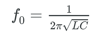
Resonant Frequency Formula
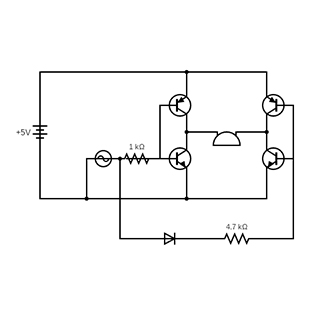
Full-Bridge Drive Circuit
This uses a single DC power supply and AC signal source to drive the piezoelectric transducer with a Vpp signal. Both positive and negative pins of the transducers are each connected to a set of transistor switches with an AC signal, or its inverse connected to the bases as shown. This configuration creates 2 independent paths for the current to flow with no overlap.
Positive to Negative Path
When the AC signal is high, the transistors create the above path for the current to flow.
Negative to Positive Path
When the AC signal is low, the opposite happens and lets the current flow through the piezoelectric transducer in the other direction.
The benefit to this drive circuit is that you can take advantage of the full range of motion of a piezoelectric element without using a high voltage AC source. The DC source can also effectively provide twice the amplitude in this configuration.
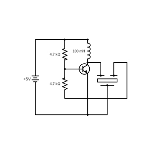
Feedback Piezoelectric Drive Circuit
Piezoelectric elements/transducers can come with a feedback pin. To utilize this additional feature, the Feedback Piezoelectric Drive Circuit can be used. This circuit requires only a DC power supply. Instead of an external AC signal, the unit can generate its own. The main benefit of a feedback piezoelectric transducer being added loudness associated to the added flex of the disk within the feedback line.
The feedback pin of the piezoelectric transducer is fed back to the base of the transistor. As the piezoelectric element flexes, the voltage output at the feedback pin changes and the voltage at the base of the transistor will also change as a result. This causes the transistor to turn on and off and function as an AC signal to the piezoelectric transducer. There are dedicated ASIC (Application Specific Integrated Circuits) used to help consistently and reliably drive feedback transducers.
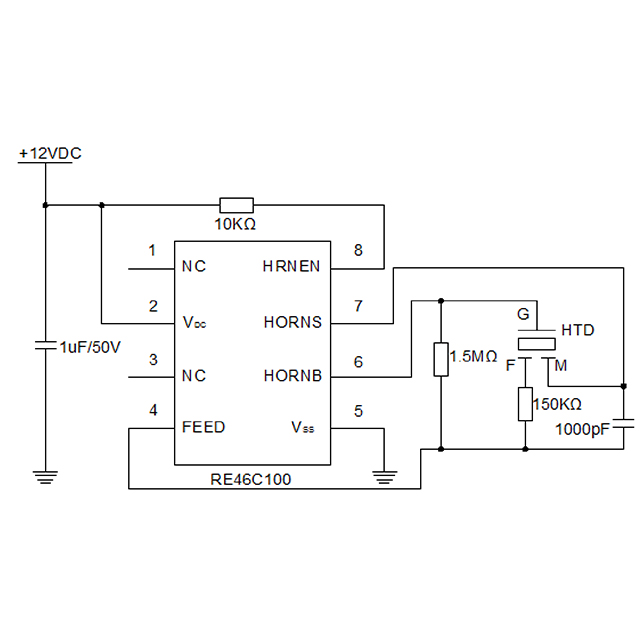
Feedback Circuit with ASIC
Speaker Design Integration
This quick-start guide has five of the most common design considerations for integrating speakers.
The minimum opening percentage for a speaker grille is a consideration that depends on various factors, including the speaker's design, the type of grille material used, and the intended application. In general, a speaker grille should allow for sufficient airflow to avoid affecting sound reproduction adversely.
While there isn't a specific universally defined minimum opening percentage, a guideline often followed in the industry suggests that the grille opening should be around 50% or more of the total surface area. This ensures that the grille doesn't impede the movement of air generated by the speaker, which is crucial for proper sound reproduction, especially in low-frequency ranges.
However, it's important to note that some speakers are designed with specific grilles that are acoustically transparent, allowing sound waves to pass through with minimal interference. In such cases, the grille design and material are optimized to have a minimal impact on sound quality.
Ultimately, the optimal grille opening percentage may vary depending on the speaker's specifications and the preferences of the designer.
Any speaker assembly has the potential to achieve an IP rating if an IP rated mesh is incorporated on the grille. Many speaker diaphragm and surround materials will of themselves achieve an IP rating though water drainage should be considered.
A designer has the option of many chamber types which will offer unique speaker performance. The design can be very complex and involved and only a basic approach will be provided here. The most common and straight forward design types are sealed and aperiodic. For a sealed chamber design, thrice the volume of the speaker should be included into the chamber. Thiele Small parameters can be provided for all speakers at customer request if a more advanced design methodology is desired.
Two mounting environments need to be considered, the speaker to the overall assembly and the chamber to the speaker.
A. Two methodologies can be used to mount the speaker to eliminate vibration either a gasket stack-up or a glue joint. This guide will only discuss the gasket design as this is the preferred methodology for customer application and provides enhanced reliability for a manufacturing environment not designed to produce speaker assemblies.
- A typical gasket stack-up for the front face of the speaker uses a compressible gasket with a double-sided adhesive and pull tab mounted to the speaker front face. A typical gasket stack-up for the rear face of the speaker uses a compressible gasket mounted either to the speaker magnet or outer rear perimeter.
- Speaker selection can be made to include screw bosses for mounting to create the needed compression.
B. The same two design concepts applied to the speaker can be applied to mounting the acoustic chamber. The main intent when mounting the chamber is create an air-tight seal along the mounting joint.
When designing methodology for wire exiting, the same methodologies employed for the speaker and speaker chamber can be applied. The design will incorporate a slot for the wires to be placed during assembly. The slot must then be air sealed either via a rubber boot placed around the wire, a compressible gasket placed over the slot or a glue joint.
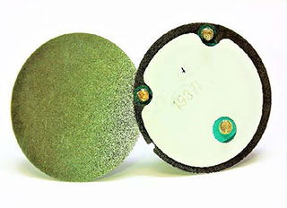
Piezoelectric Elements Overview
This quick-start guide has some of the most common design considerations for integrating piezoelectric elements.
A Piezoelectric Element, or Disk (often called a ’Bender’) is the most basic type of electronic component used to produce sound.
- Low power consumption.
- Inexpensive.
- Used in many electronic products such as consumer, fire, & safety and medical applications.
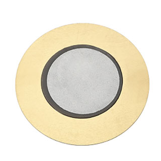
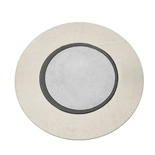
- Typically are round using metallic disk with a layer of ceramic that is ’sandwiched’ by an electrode.
When voltage is applied, the disk vibrates at a given frequency and produces sound. More voltage means a louder disk. The sound can be:
- A steady ’Buzz’ or a ’Beep’.
- A series of several notes, often called ’Sing-Tones’.
The three basic types of metals used are Brass, Nickel Alloy and Stainless Steel.
1) BRASS is the most common and least expensive.
2) NICKEL ALLOY is used if exposed to high humidity and/or extreme temperatures changes.
3) STAINLESS STEEL withstands contact with harsh chemicals, solvents, salt water, etc.
For a piezoelectric to make sound, it needs to sit atop a housing called a ’Chamber’. If placed on a flat surface, it will not be able to properly flex to produce sound. The chamber (a ’Helmholtz Resonator’) is typically designed to match the resonant frequency of the piezoelectric disk.
- Metallic Disk
- Ceramic Disk
- Chamber

Can be glued to the chamber or come with a peel-off adhesive.
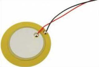
Can have lead wires and a connector.
Can have springs to increase reliability.
Can connect via contact pins on a mating PC board.
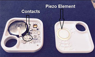
The best example of a piezoelectric application is a smoke detector.
Other examples:
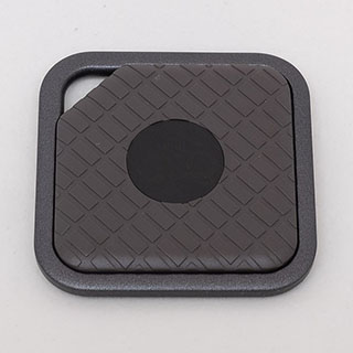
Key Finders
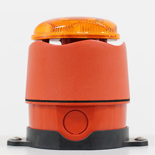
Alarm Beacons
Handheld products

POS Terminals

GPS Trackers

Training Collars
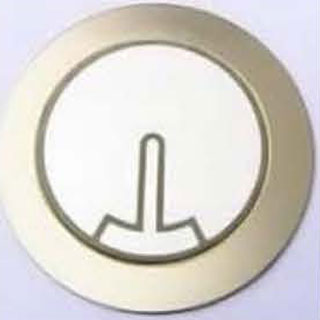
Feedback Element
Piezoelectric disks with a third wire, also called ’Self Driven’, have a Feedback Electrode and can be driven with only a transistor and three resistors.
Bi-Morph
A ’Bi-Morph’ Piezoelectric disk has the electrode and ceramic layer on both sides of the metal disk. When pulsed, a ’Push-Pull’ effect is created making the piezoelectric slightly louder.
A piezoelectric disk can also be used as a low-cost switch. When ’stressed’, a piezoelectric disk creates a small amount of voltage that can trigger a microprocessor or microcontroller.
The smaller the piezoelectric, the higher the frequency. The larger the disk, the lower the frequency.
Approximate Ranges:
- 9mm to 15mm — 6,000 Hz to 9,000 Hz
- 19mm to 27mm — 3,600 Hz to 5,400 Hz
- 27mm to 32mm — 2,300 Hz to 3,300 Hz
- 35mm to 48mm — 1,900 Hz to 2,300 Hz
Sound Transducers Overview
This quick-start guide has some of the most common design considerations for integrating sound transducers.
There are two standard sound transducer types, Piezoelectric and Electromagnetic (’EM’). These transducers are a more robust solution for the customer from a piezoelectric disk.
- Like a piezoelectric disk, they need to be driven from a simple PC Board circuit
- They are packaged in SMD, Thru-Hole or wire leaded housings.
- They are optimized to perform best at specific frequencies.
Piezoelectric sound transducers use a piezo disk. When voltage is applied to the disk, the disk vibrated and makes a sound.
Electromagnetic sound transducers emit sound using magnetic material, a wire and a metal disk. When a current is passed through the wire, the magnetic material interacts with the disk and makes the disk vibrate to make sound.
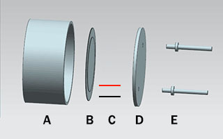
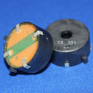
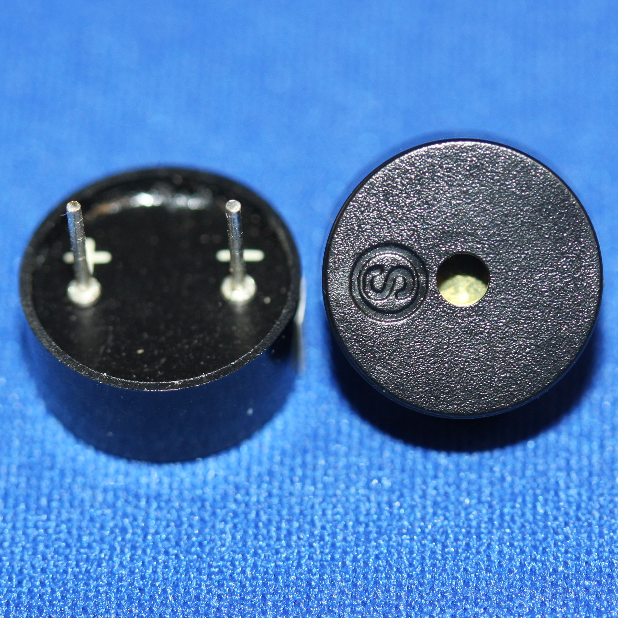
PIEZOELECTRIC TRANSDUCER
- Outer Case
- Piezoelectric Device
- Internal Wiring
- Bottom Case
- Termination
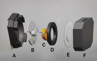
ELECTROMAGNETIC TRANSDUCER
- Bottom Case
- Core
- Enameled Wire
- Magnet
- Diaphragm
- Top Case
- Low power and acheive as low as 1mA current draw at rated power, often even lower.
- Most designs are IP capable.
- Will operate at any low-level voltage
- Smaller packages can acheive up to 70 dB at 10 cm with rated voltage.
- The larger the package size, the lower the output frequency.
- Great in harsh environmental conditions.
9 to 17 mm ➭ 3.2 to 4.0 kHz
20 to 26 mm ➭ 4.0 to 5.5 kHz
30 to 65 mm ➭ 1.0 to 4.0 kHz
Most Piezoelectric Transducers are IP capable on the front diaphragm, some even up to IP68. IP67 means the transducer can be submerged into a body of water up to a meter deep for 30 minutes and still operate. IP68 guarantees protection in water up to 3 meters deep also for 30 minutes and still operate. Both IP ratings are dust proof.
Applications are endless! Focus should be on any hand-held / consumer products, medical and industrial devices. Also look at all keypad applications.
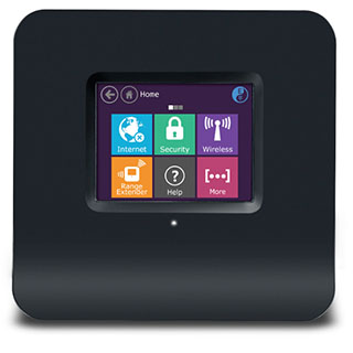
Portable WiFi
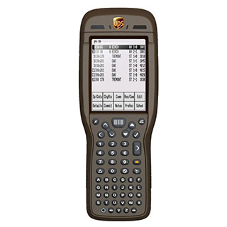
Handheld Products
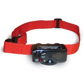
Training Collars
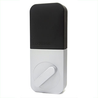
Digital Door Locks
Electromagnetic Transducers are used when a design has tight width constraints or low frquency requirements. They consist of eight components that are quite small and are made with highly automated coil winding and assembly equipment.
- Upper Housing
- Magnetic Plate
- Diaphragm
- Permanent Magnet
- Coil
- Yolk Plate
- Lower Housing
- Terminals
- The minimum overall width can be as small as 3.2 x 3.2 mm.
- SPL’s range from 68 dB to 95 dB at 10 cm with rated power.
- Can acheive louder outputs at lower frequency ranges.
- Consume more power when compared to Piezoelectric transducers.
3x3 to 7x7 mm ➭ 1100 to 4000 Hz
8x8 to 12x12 mm ➭ 2100 to 4000 Hz
14x14 to 25x25 mm ➭ 950 to 3200 Hz
Applications are endless! Focus should be on any wall powered device where there is no limit on power, or a product with limited PCB space.
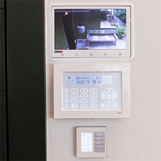
Home Controls

Gaming Consoles
POS Terminals
Most packages can be customized to achieve the desired form factor.
- Wire Leaded units can have the wire length, wire guage and connector customized. (All Volumes)
- SMD units can have the footprint updated to meet a specific landing pattern. (High Volume Opportunities; Minimum 400K Pieces EAU)
- Thru-Hole units can have the pin spacing modified. (High Volume Opportunities; Minimum 250K Pieces EAU)
SMD
Thru-Hole
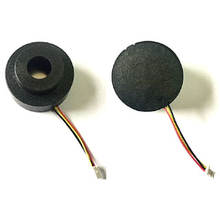
Wire Leaded with Connector
Finding Safe Harbor for Electronic Audio Components
One of humanities greatest achievements is harnessing the power of aquatic environments for travel, commerce, and luxury. From engine heat indicators to GPS systems, the parameters to design a cutting-edge audio component for harsh aquatic environments requires meticulous calculations, material selection, and rigorous testing. This technical report provides an overview of how Challenge Electronics Engineering Team designs products with nature in mind, resulting in rugged, long lasting, and distinguishable audio components.
Click Here for Technical Report
Practicing Sound Medicine
Whether you are visitor or a medical professional, the incorporation of audio devices is critical for a health center to operate efficiently. From insulin pumps, timed medicine dispenses and cardiac emergency equipment, optimizing the right audio tone into your design will allow medical personnel to respond quicker to the situation. This technical article will outline the benefits of audio signal vs size, the differences in the industry standard signal tones, as well as Challenge Electronics innovative and proprietary sound bending tone, the PinPoint Alert System.
Click Here for Technical Report